Blood, Sweat, and Sawdust

Going against the grain

Category: Tools

A Bogg’s Inspired Shavehorse: The Base

Somethings go as planned.  Others do not.  The base of my shavehorse followed the latter.  What seemed a simple, straight-forward glue-up ended up complicated and frustrating.  However, in the end everything worked out and the base is complete.

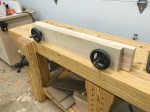
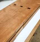
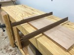
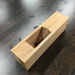
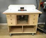
At first glance, the base seems simple enough.  Two sides, sandwich together with spacers between.  The rear legs fit into angled dados, and everything is reinforced with pegs.  However, the pegs fit somewhat tightly.  So, I was unable to do a full-fledged dry-run of the glue-up.  As a result, I ran into an unforeseen problem.

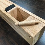
I lathered everything up with glue and went to town.  The front went together easy enough.  However, I immediately had problems with the rear.  First, I aligned both sides with the rear spacer, and drove the peg through all three pieces.  Then, I started with the legs.  Unfortunately, the legs fit a little too tight, so I started to drive them home with a dead-blow mallet.  After a few moments, I realized I wasn’t making progress.  Every time I drove the mallet, I was only shifting the legs; the space between them wasn’t growing any smaller.  I began to fear that I was running out of time.

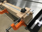
Fortunately, quick thinking and just the right amount of panic led to a solution.  I clamped a stop on one side of the legs, and drove with the mallet from the other side.  When they were close enough, I used two clamps to cinch them the rest of the way.  Crisis averted!

With the shavehorse’s base complete, I will move on to the ratchet, key, treadle, etc.  Stay tuned.

Making a Boggs Inspired Shave Horse

Chair making deeply interests me.  The sensuous curves of a Maloof rocker and practicality of a ladder back captivate me.  Despite this, I have yet to build more than a few Adirondack chairs.  So, I signed myself up for Jeff Miller’s chair building class in November.  In the meantime, I decided to learn all I could about chair making.  Along the way, I determined that I would need a shave horse.

You use a shave horse to hold chair parts for shaping with a draw knife or spoke shave.  It consists of a seat and clamping apparatus.  A good shave horse allows the user to easily adjust clamping pressure, while maintaining a comfortable seating position

So, I scoured the Internet for information.  Eventually, I decided to build a horse similar to one Brian Boggs designed several years ago.  In case you didn’t know, Brian Boggs is a talented chair maker from Asheville, North Carolina.  His shave horse sits on three legs, uses a foot operated treadle, and clamps with an adjustable lower jaw.  Additionally, the user builds the device to suit his or her own body.

Shave Horse

I have already milled most of the lumber.  I have shaped the sides and started on the legs.  Once the base is complete, I will install the jaws, treadle, and seat.  If all goes well, I should complete the horse within a week.

Stay tuned for progress.

A Bench Crafted Moxon Vise

While building my tool cabinet, I discovered a major issue with my workbench.  It sits too low for detailed work.  After several nights of dovetailing, I began to develop a back ache.  I needed something that would bring my work closer to my eye.  I needed a Moxon vise.

A Moxon vise is a twin screw accessory vise that sits on top of your workbench.  Joseph Moxon described such a vise in his quintessential “Mechanick Excercises”.  As a result, others started referring to similar devices as “Moxon vises”.  The vice fastens to your benchtop using holdfasts or clamps and is stored below the bench top when not in use.  Since, I’ve been very happy with my Bench Crafted leg vise hardware I decided to give their Moxon vise hardware a shot.  The Bench Crafted Moxon vise hardware consists of two handwheels, two acme screws, four nuts, and a nice piece of suede.  Everything in the kit exudes quality.

The Build

First, I milled up some 8/4 ash for the jaws and stabilizer.  Then, I drilled a counter bore in the fixed jaw.  The counter bore will receive one of the large nuts.  Next, I drilled the hole for the acme screws.  Then, I drilled elongated holes in the moveable jaw and attached a stabilizer to the back of the fixed jaw.  That’s it.  The basic build is very simple.  However, give me enough time and I will overthink everything

Instead of the basic square mortise for the nut, I decided to try a cleaner, hexagonal mortise.  To start, I made my counter bores slightly smaller than the provided nut.  This allowed me to thread a nut onto one of the acme screws and place the nut over the counter bore.  Next, I traced the nut on to the fixed jaw using a marking knife.  Then, I chopped out the corners with a sharp chisel.  I think the results speak for themselves.

Additionally, I decided that I wanted a nice bevel on the front of the movable jaw.  And, what better compliments a stopped bevel than a lamb’s tongue transition?  To create the lamb’s tongue transition, I started by making a template.  Then, I used the template to mark out its location.  From there, I used a carcass saw to sever the grain at the transition.  Then, I simply hogged out the waste with a chisel and mallet.  Finally, I cleaned things up with a rasp and sand paper.  I over cut in a few areas, but I think this turned out well for my first attempt.

I hate contact cement.  So, I searched for an alternative.  During my search, I discovered adhesive cork board.  My local Home Depot carried it.  So, I decided to give it a shot.  I only attached the cork to the inside of the movable jaw, but I think this will be sufficient.  It’s easier to apply than suede and without the noxious fumes of contact cement.  Finally, I applied a few coats of shellac and wax to the outside faces of the vise.  I’m very happy with the results.  The Bench Crafted Moxon vise hardware does not disappoint.

A Hand Tool Cabinet: Finishing Touches

Fertig.  Finito.  Terminado.  The tool cabinet is finished.  Well, it’s not finished finished.  It’s good enough for now.  I need to make drawers for the plane gallery and a few more tool holders.  However, I have completed the majority of my checklist.  In fact, most of my hand tools are now in the cabinet.

Plane Gallery

Since my last post, the only big item I needed to complete was the plane gallery.  I made the gallery from half inch birch plywood and faced it with cherry trim.  I recessed the top towards the right side with a gentle curve.  Additionally, the gallery dividers curve to sit flush with the top.  This allows you to easily remove items from each bay.  One day, I will make drawers for the two vertical bays on the left.

Aside from the plane gallery, I built a few more tool holders.  You can see them in the image below.

Completed Tool Chest

That’s all for now.  Although, I may write one more post detailing the drawers.

I will build a Moxon vice using Bench Crafted’s hardware for my next project.  So, stay tuned.

For my previous post on this project click here: Tool Holders and Interior Doors


A Hand Tool Cabinet: The Case

This project marks a milestone for me.  It is my first project that goes heavy on the joinery.  The hand tool cabinet includes nearly 50 dovetails, through tenons, slip tenons, and rabbets.  As a result, it is proving to be a valuable learning experience.

While power tools speed the build process, hand tools prove indispensable.  Most noteworthy, is the humble chisel.  To say that this project has honed my chisel skills would be an understatement.  Chisels are vital for paring dovetail pins, chopping to baselines, and paring shoulders.

The Build

I began with the tail boards.  I cut these at the table saw using a special blade (click here for more information).  Then, I used the tail boards to mark the location on the pins on the pin boards.  Next, I cut the pins using a dovetail saw.  I removed most of the waste with a fret saw.  Finally, I used a trim router to remove the rest of the waste.  I’ll write a follow-up article on this later.

With the dovetails complete, I moved on to the tenons for the shelf.  These are through tenons, so layout is critical.  I cut the tenons on the table saw, and used the same router method mentioned earlier to get to the baseline.  Then, I used the tenons to mark the mortise locations.  I drilled out most of the waste at the drill press.  Finally, I cleaned up the rest of the waste with a sharp chisel.  I started fitting the tenons from the outside to avoid overshooting and producing gaps.  I did end up with a few minor gaps.  However, working from the outside definitely helped.  I believe this was the most difficult part of the build, so far.

With the case joinery complete, I cut the rabbet for the back at the table saw, and ganged up the hinge mortises.  For the hinge mortises, I used my cross-cut sled and a spacer.  I cut the spacer the same length as my hinges minus the kerf of my saw blade.  Then, I used the spacer with stop blocks to zip through the mortises.

Finally, I finished all of my surfaces with a wash coat of shellac and glued everything up.  Having the back already cut really helped to square everything up.  Before starting on the doors, I went ahead and completed the plane till.  I think it looks great so far.

Next up, doors and more tool storage.  Stay tuned for more of the hand tool cabinet.

You can check out my previous post here: Lumber Selection

Additionally, you can check out my next post here: The Doors


Better Winding Sticks

I built my first pair of winding sticks a couple of years ago.  Back then, I worked primarily with hand tools.  Today, I prefer power tools.  However, I still need a good pair of winding sticks.  Recently, I discovered just how poor my first pair were.  That sent me on a path to build better winding sticks.

My old sticks suffer from poor visibility.  Consequently, I bored holes at the ends of one stick.  It turns out that the holes don’t quite line up.  Additionally, the sticks aren’t the same height.  All of this stems from the fact that I had limited tools and skills at the time when I built them.

Better Winding Sticks

So, I scoured the Internet for good ideas.  It turns out, there are quite a few.

  1. First, I picked up the idea to use quartersawn walnut, with maple inlay from Chris Schwarz.  This provides a lot of contrast for better visibility.
  2. Paul Sellers provided me with the idea to bore a hole through the center of each winding stick.  This allows you to easily center the winding stick on the board you’re checking.
  3. Finally, everyone seemed to use a beveled design.  I believe the benefits of this are two-fold.  First, it helps the winding sticks reflect more overhead light for better visibility.  Second, it increases stability by removing some of the weight at the top of each winding stick.

Next, I took a trip to the lumber yard.  It took some digging through the boards to find one that qualified as quartersawn.  In the end, I found what I was looking for.  I rough milled the board and let it sit for a few days to acclimate.  Then, I jointed the rough sticks and thicknessed them to 5/8-inch.  Next, I cut the bevel on the band-saw.  After cleaning up the bandsaw marks, I started work on the inlay pieces.  I cut these from some maple scraps I had lying around.  Then, I used the inlay pieces to mark their respective mortises.  I cut the mortises using a trim router, and cleaned them up using a chisel.  After gluing up the inlay pieces, I bored the holes at the drill-press.  Finally, I cleaned up the faces with a smooth plane and applied a couple of coats of tung oil.

I think the turned out well.  They’re much more accurate and easy to read than my old ones.  Additionally, the inlay turned out okay for my first try.  In conclusion, my attempt at making better winding sticks was a success.


A Review: Make a Wooden Smoothing Plane

I spent the last six months building the workshop.  Yes, life blessed me with an amazing opportunity.  However, I grew tired of drywall, cabinets, and electrical.  I wanted a fun project.  So, when I stumbled across Scott Meek’s video, “Make a Wooden Smoothing Plane”, I decided to give it a shot.

You can buy Scott’s video as a digital download or DVD.  It provides over two hours of detailed instruction.  In addition, Scott includes a Sketchup template and detailed drawings.  The video starts with wood selection and milling.  Then, it walks you from shaping to troubleshooting.  Additionally, Scott provides you with excellent plane making tips along the way.  Furthermore, “Make a Wooden Smoothing Plane”, puts it in simple English that’s easy to follow.

Heck, even I was able to follow along.  In fact, I was able to make my wooden hand plane in just a few days.

The entire process is pretty simple.  First, you mill your cheeks and center assembly.  Then, you dry assemble the plane body.  Next, you cut your throat and ramp.  Then, you glue everything together.  Finally, you shape the plane body and troubleshoot.  While the most difficult part was cutting accurate tenons on the cross-pin, my first wooden plane was a success.

My only complaint, is that Scott doesn’t delve into plane iron selection or troubleshooting.  I choose the 2-inch wide, by 4 1/2-inch long iron from Ron Hock.  In conclusion, I highly recommend Scott Meek’s, “Make a Wooden Smoothing Plane”.  It provides excellent instruction and it’s a fun project.

You can find it at www.shopwoodworking.com

Improving the Porter Cable Drill Press

The 15-inch Porter Cable drill press is an excellent value.  It’s cheap, accurate, and powerful.  However, it has one huge drawback for the woodworker: the table.  It sucks!  As a result, I made an auxiliary table to help me get the most out of this tool.

Unfortunately, there isn’t a lot of information on making an auxiliary table for this model.  So, I inspected the drill press and came up with a game plan.

Porter Cable Drill Press Table

My design consists of two sandwiched pieces of melamine, and oak edge banding.  It also has a slot in the middle for replaceable inserts.  Finally, it has t-tracks for a fence and hold-down.  I used a plunge router to create the slot and a dado stack to fit the t-tracks.  Easy stuff.  The hard part is mounting the new table to the existing one.

Ultimately, I decided to mount the auxiliary table using two hex bolts.  The bolt heads are countersunk to keep the surface obstruction free.  Since the existing table doesn’t have mounting holes, I drilled them myself.  This was easier than I anticipated.  As a result, the table is easy to remove and adjust.

I built the fence from scrap melamine.  The fence attaches to the table with star-knobs and bolts.  I also added a hold-down.  Now, I no longer have to hold my work-piece with my bare hand.  Yay safety!

While still in the workshop, I made about 15 zero clearance inserts.  I cut these from the same material as the top.  As a result, they sit perfectly flush.  Hopefully, I won’t have to make any more for some time.

The new table presents a big improvement to the Porter Cable drill press.  So far, my only concern is the height of the fence on the right.  With smaller material, the drill-press handles may interfere with the fence.  If this becomes and issue, I’ll just cut a notch in the fence.


The Mortise Jig

The Idea

Above everything, I want to create beautiful and unique furniture.  The furniture which draws my attention has a common theme: mortise and tenon joinery.  Ideally, I would create mortises with a dedicated hollow-chisel mortiser.  Unfortunately, I don’t have the space or funds available for such a wonderful tool.  As a result, I have determined that my best course of action is to use the plunge router for mortising.

To improve speed and accuracy, I followed Jeff Miller’s advice and built mortise jig.  I followed Jeff’s design fairly closely, but made some minor improvements to the original plan.  For example, I added a t-track and adjustable stop blocks for better repeat-ability.

The Design

The jig is simple in design and easy to make.  It consists of a platform, a track, and a pair of hold-down clamps.  I milled an auxiliary fence for my router at the same time I milled the parts for the track.  This ensures a perfect fit to guide the router.

A 8/4 white oak board with too many knots for furniture sat on my lumber rack.  It had just enough straight grain to mill up the parts for the jig.  I laminated two pieces to make the platform.  Then, I cut a dado for the t-track.  I built the guide by resawing another strip of oak.  The resawed pieces produced three 3/4-inch strips: two for the guide and one for the auxiliary fence.

I glued the guide pieces together.  However, I did not permanently attach the guide to the base.  It attaches using 3/8-inch bolts that are also used to secure the hold-down clamps.  This allows me to replace the track if it wears out over time.

The Results

I eased the sharp edges with a block plane, and applied paste wax to the fence.  So far, the jig works extremely well.  I plan to use it on a few projects that I have coming up.  Stay tuned.


Building the Perfect Router Table

I experienced a love hate-relationship with my small, bench-top router table.  I regretted selling it, but it was a pain to use.  I promised myself that I would build a better one as soon as I got moved into the new shop.  That’s exactly what I did.

Router Table

Finding inspiration in Norm Abram’s Deluxe Router Station, I designed a custom table that exceeds the capabilities of the best pre-built options.  It has an integrated lift and a dedicated motor (no more pulling the motor for plunge duties).  It also has a large top, sturdy fence, and excellent dust collection.  Better yet, it has lots of storage and is completely mobile.

I made the base from 3/4-inch birch plywood.  I constructed the case using dado joints.  This makes a sturdy base that is easy to glue-up.

I made the top by laminating two sheets of MDF and covering that with a thin sheet of laminate.  Then, I trimmed it with oak and cut dados for a miter slot and t-track.  I finished the top by cutting the hole for the router lift.

I enclosed the motor with a small frame-and-panel door.  The frame is from oak and the panel is a small piece of Lexan.  The door is held in place using magnetic door stops.  I love that you can see all the mechanics through the Lexan panel.

The table collects dust using a 4-inch port on the base and a 2.5-inch port on the fence.  I built a small ramp inside the base with a hood below.

So far, I’m very happy with the build.  The Jessem Mast-R-Lift works flawlessly and it’s nice to have a powerful, dedicate router motor.

I have included the SketchUp at the following link: Router Table